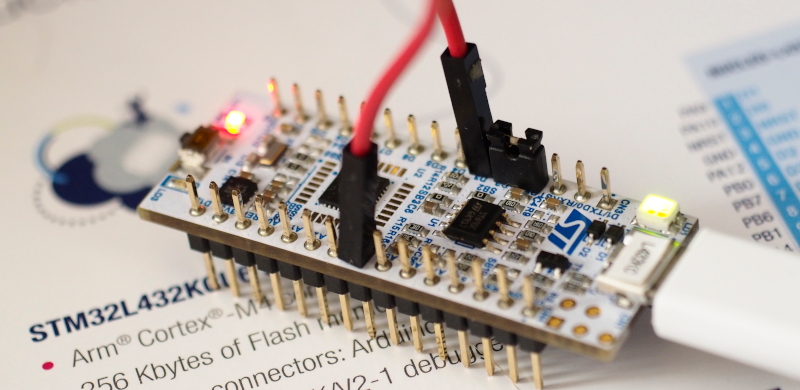
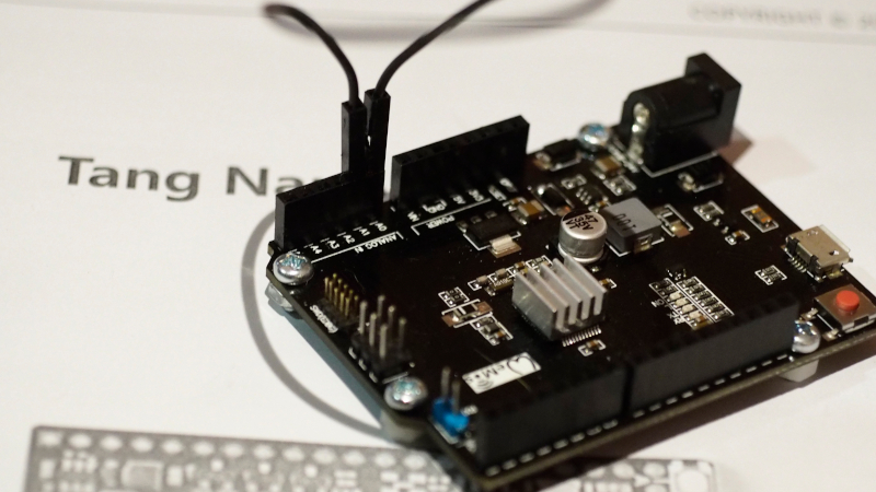
From reading the article Using STM32 Core Support for Arduino for Board Nucleo L432KC by Ajarn Rewat Siriphokapirom, we have provided the board to test and connect the pin for sending data output DAC to ADC as shown in Figure 1 to test the operation of the DAC and ADC of the board by using the working code like the ESP32 microcontroller board, SAM-D21 and LGT8F328P. Let’s get started.
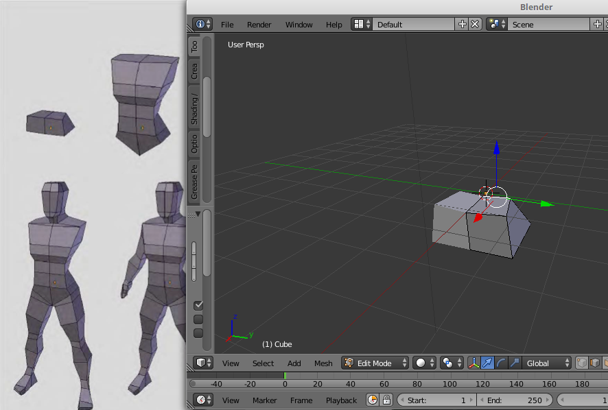
This article is a record of the process of forming a low polygon with Blender, a free distribution software, and revealing the code. It is currently version 2.93.6 LTS, starting from the box and cutting off the left side. After that, use a Mirror Modifier to make the left and right sides the same. Making adjustments to only the right side, causing the left side to affect as well. After that, arrange the shape as shown in Figure 1.
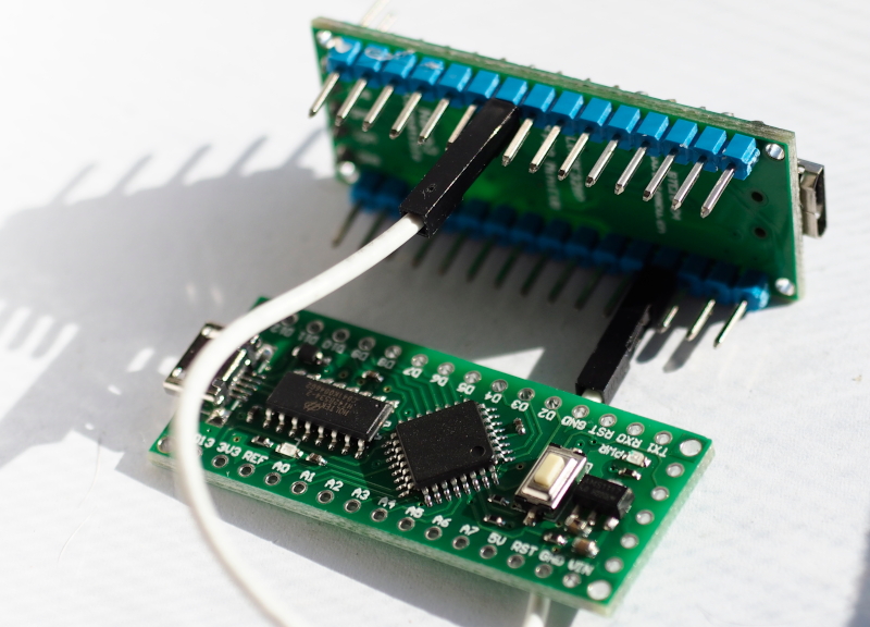
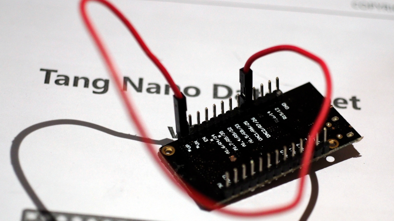
This article is a continuation of the previous article introducing the LGT8F328P board and its use of ADC and DAC. By focusing on the use for the chip LGT8F328P, which is different from the SAM-D21 in that it uses pin D4 as a pin that serves as DAC0 and the DAC circuit has a resolution of 8-bit. The output can be from 0 to 255. The ADC sector uses pins A0, A1, … normally and has a resolution of 12 bits. Therefore, in this article, the connection pins from A0 to D4 are used in the experiment as shown in Figure 1.
This article introduces the ESP32 and SAM-D21 microcontroller board to learn how to use ADC (Analog to Digital Converter) and DAC (Digital to Analog Converter) instruction by connecting the DAC pin to ADC as shown in Figures 1 (Connect A0 to A1 of Board SAM-D21 ) and 2 (Connect Pin GPIO26 to GPIO36 of ESP32) to send data to DAC and have ADC read it back. Then send the results out to the serial port for display with the Serial Plotter, which is an example program to send 3 types of data, which is a zigzag graph, triangular graph and waveform graph from the sinusoidal function
Figure 1 SAM-D21 with A0 connected to A1Figure 2 ESP32 with port 26 connected to port 36
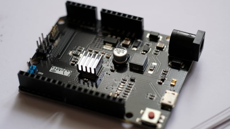
This article introduces a microcontroller board based on Microchip’s ATSAMD21G18 chip based on 32-bit ARM architecture, Cortex-M0+ family in the form of a board based on the Arduino Uno family as shown in Figure 1.
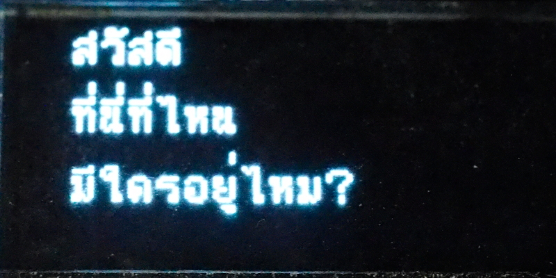
From the article on how to use u8g2 that can render Thai string through the drawUTF8() function of the u8g2 library, the rendering is not correct as shown in Figure 1, therefore, the code of libraries needs additionally adjusted to render correctly as in Figure 2.
Figure 1 drawUTF8() display before adjustmentFigure 2 drawUTF8() after adjustment
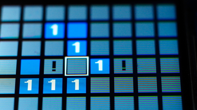
This article is an experiment to create a Simple MineSweeper as shown in Figure 1, using an ESP32 microcontroller board with a 1.8″ REDTAB st7735 display. The display resolution is 128×160, the same hardware as Simple Tetris [Part 1, Part 2 and part 3] mentioned earlier, still using MicroPython as the main. The explanation starts step by step from screen generation, randomization, counting, motion control, scrolling the options frame turn off visibility, establishing a relationship between identifying where the bomb is likely to be, picking open and counting points at the end of the game.
Simple MineSweeper is one of the first games we’ve been imitating to study ideas and develop programming techniques since the DOS era and the GUI-based Windows operating system DOS, which was written and worked on the DOS operating system at the time, change the mode to graphics mode to contact with mouse and draw pixels by yourself (It’s the same thing as writing on the ESP32 microcontroller board, but it doesn’t have an operating system to use) So let’s get started.
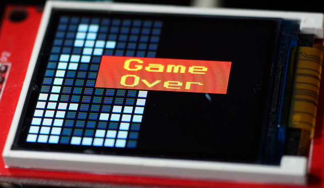
The final article on making a Simple Tetris game using MicroPython and an esp32 microcontroller, as written in parts 1 and 2 of the first two articles, is described in the article below. Readers learn to design data structures, drawing the seven types of falling objects and controlling them to move left, right, and rotate. The second article has the object fall from above and keep the object’s position state. And in this article, the falling objects can be stacked along with moving left, right, and rotating the object will check for collisions with previous objects that have fallen before. Also, check if the object falls to the bottom if there are any rows without spaces. If any rows with no spaces are found, they will be deleted. And finally added a section to check the end of the game in case there is no place for objects to fall and move again as in Figure 1, ending our simple game making process.