[EN] How to build MicroPython for esp32-C3.

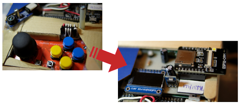
This article discusses the previously recommended compiling (build) and use of MicroPython for esp32-C3 microcontrollers. The procedure is the same as for compiling for esp32-s2. In addition, we have solved the issue of RS232-to-USB from the board using CH340 to external pin using CP2102 instead and connecting the display module with OLED as Figure 1.

Figure 1 ESP32-C3 with OLED and external pins

[EN] How to build MicroPython for esp32-s2.

This article discusses compiling and using MicroPython for an esp32-s2 microcontroller based on the TTGO ESP32-S2 V1.1 or TTGO ESP32-S2-WOOR V1.1 board with a Type-C USB port and supports operation via CH340C and OTG by using a dip switch as shown in Figure 1, enabling MicroPython to be used because the chip program uses the CH340’s circuit programming and Python programming requires a port that works like OTG

TTGO ESP32-S2 V1.1
Figure 1 TTGO ESP32-S2 V1.1

[EN] ESP-IDF Ep.10 : Control the Servo Motor with LEDC.

This article discusses the implementation of a servo motor module using the ESP32’s GPIO that outputs a digital PWM signal or Pulse Width Modulation or an LEDC (LED Control) which enables frequency band generation or adjust the proportion of status 1 and 0 in 1 waveform with a frequency of 50Hz using the experimental board as shown in Figure 1.

(Figure. 1 LEDC connection)

[EN] Control movement from a joystick via WiFi with MicroPython.

This article is based on the article programming a client/server for a weather station over a wireless network or WiFi to modify from reading data from sensors to joystick shield (Arduino Joystick Shield) so that it has become a wireless game controller using MicroPython and an ESP32 microcontroller as shown in Figure 1. It is possible to control the movement of objects in the display via a ST7735 TFT screen connected to another ESP32. It will be found that the Python implementation of MicroPython is applicable in this example. And with an easy-to-write language and code that can be modified without recompiling and uploading, it’s easy to write prototype code for further development at a higher speed.

Control movement from a joystick via WiFi
(Figure. 1 Our board)

[EN] ESP-IDF Ep.9 : LEDC (PWM) Output

This article discusses the use of the ESP32’s GPIO to output digital signals such as PWM or Pulse Width Modulation or LEDC (LED Control), which enables frequency generation or adjusts the proportion of 1 and 0 states in 1 waveform. Thus, in the absence of the DAC, we can still adjust the average voltage at that pin as needed and it can be applied to control servo motors as well. Therefore, in this article, we will learn how to use PWM and apply it to frequency transmission instead of DAC (from the previous article) and LED dimming using the experimental board as shown in Figure 1.

LEDC / PWM Labs.
(Figure. 1 Our LEDC)

[EN] ESP-IDF Ep.8 : DAC Output Part 2

This article discusses the use of the ESP32’s GPIO as an analog signal output through the 8-bit DAC module of the ESP32 microcontroller. In this article, we use Cosine wave generation to output the analog signal of the microcontroller through the speaker and show the waveform obtained from the oscilloscope display. The experimental board is still used as shown in Figure 1.

(Figure. 1 Connection and use of DAC examples)

[EN] ESP-IDF Ep.6 : ADC Input

This article discusses the use of the ESP32’s GPIO as an analog input. By using the voltage input circuit from adjusting values with an adjustable resistor as shown in Figure 1. So, in this article, we will learn how to use the ADC instruction of the ESP32 microcontroller and how to configure the value of ADC in menuconfig.

(Figure. 1 The implementation is illustrated with the example in this article)

[EN] How to used Arduino 2.4″ TFT LCD&Touch Shield with STM32F401?

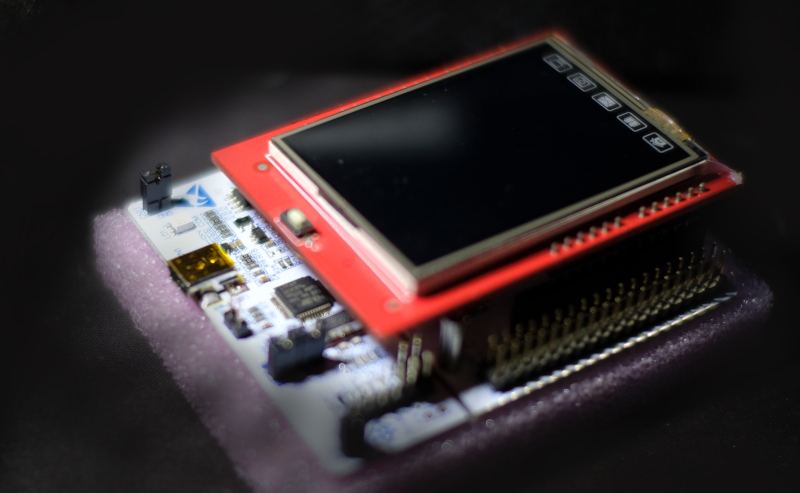
From the previous article that has used a 3.5″ display for Raspberry Pi Board to use with ESP32, we also have an Arduino 2.4″ TFT LCD & Touch Shield that is used with Arduino Uno and Arduino Mega (as shown in Figure 1. ) and want to use with a microcontroller STM32F401RET6 Board NUCLEO-F401RE and STM32F401CC (Figure 2), which are Cortex-M4 with 96KB and 64KB memory respectively, ROM memory is 512KB and 128KB, with 8 switches connected to the pin. In this article, Board ET-TEST 10P/INP (Figure 3) is used to replace the left, up, down, right, m1,m2, A and B buttons respectively.

Nucleo-F401RE+Arduino Uno 2.4" TFT&Touch Shield
(Figure. 1 Arduino Uno TFT&Touch Shield module on Nucleo-F401RE)