[EN] ESP-IDF Ep.7 : DAC Output
This article describes the use of the GPIO of ESP32 to output analog signal through 8-bit DAC module of ESP32 microcontroller by creating a zig graph (Figure 7) to the speaker module as shown in Figure 1.

This article describes the use of the GPIO of ESP32 to output analog signal through 8-bit DAC module of ESP32 microcontroller by creating a zig graph (Figure 7) to the speaker module as shown in Figure 1.

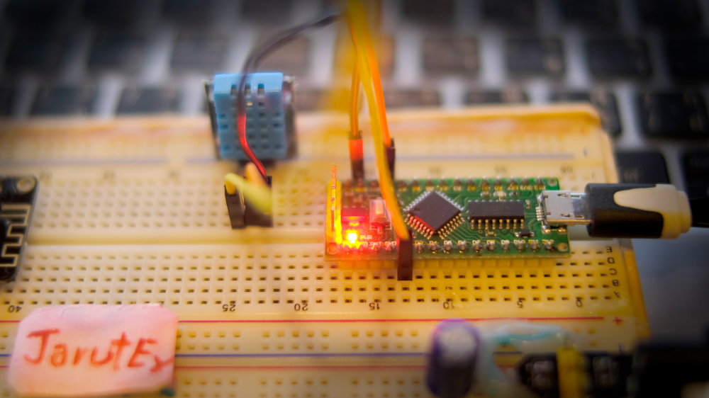
บทความนี้เป็นการเขียนโปรแกรมภาษา C/C++ กับบอร์ด Arduino Nano, Arduino Uno, LGT8F328P หรือบอร์ดอื่น ๆ และแพล็ตฟอร์มอื่น ๆ ที่ใช้ภาษา C ได้ โดยในบทความนี้กล่าวถึงวิธีการใช้โครงสร้าง struct สำหรับเก็บข้อมูลและตัวชี้ที่ใช้สำหรับชี้ไปยังตำแหน่งของหน่วยความจำ และวิธีการบริหารหน่วยความจำได้แก่ การจองหน่วยความจำ การเข้าถึงหน่วยความจำ และการยกเลิกการใช้หน่วยความจำเพื่อสร้างวิธีการจัดเก้บข้อมูลแบบลิงค์ลิวต์เดียว (Singly Linked List) พร้อมทั้งตัวอย่างโปรแกรมที่ใช้สำหรับเก็บรายการค่าอุณหภูมิและความชื้นจากโมดูล DHT11 ดังภาพที่ 1

This article discusses the use of the ESP32’s GPIO as an analog input. By using the voltage input circuit from adjusting values with an adjustable resistor as shown in Figure 1. So, in this article, we will learn how to use the ADC instruction of the ESP32 microcontroller and how to configure the value of ADC in menuconfig.

This article discusses the use of the ESP32’s GPIO to act as a digital signal import. By using the circuit of a keypad that is a switch of 8 that is made to look like a gamepad as in Figure 1.

Because we bought a 3.5″ display for the Raspberry Pi board to use and wonder if it can be used with the ESP32 board or not. Therefore, this article talks about how to use a TFT LCD Shield designed for Waveshare’s Raspberry Pi with the TTGO T8 ESP32 microcontroller via the TFT_eSPI library to display and operate a touch screen system as shown in Figure 1.

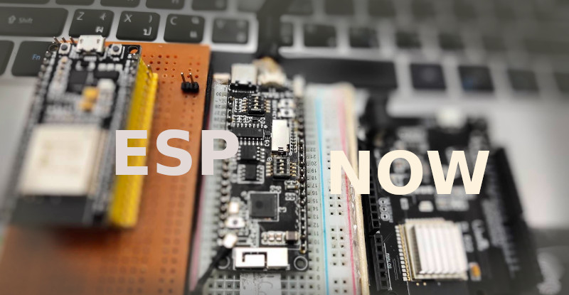
The article discusses the use of communication developed by espressif to communicate between its microcontrollers via wireless communication, as an alternative to the development of a non-linear Client/Server system. It describes the working process of working as a service provider, commander, and a set of related instructions through the Arduino core, along with explaining the working examples that come with both Arduino cores, which are basic and Multi-slave, which can be applied variously.

This article discusses setting the GPIO and sending the digital status 0 or 1 to the port, starting with the LED on and off by connecting to the external LED circuit of the board as shown in Figure 1.

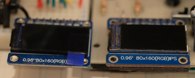
This article describes setting up the Arduino’s TFT_eSPI library to use the ST7735s-controlled TFT LCD that was written as an example in a previous article in Python. We found that there are 2 0.96″ LCD IPS ST7735s models, which are GREENTAB160x80 and REDTAB160x80. Both modules differ in the spacing between them, as shown in Figure 1. This article uses the ESP8266, ESP32 DO-IT DevKit version with ESP32CAM and STM32F103C8T6. It is a board to test the functionality of the program.

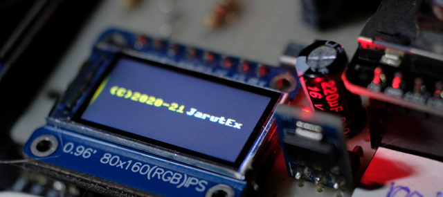
This article is an update of the st7735 library file for Micropython by Billy Cheung (accessed 2021-09-07) published on github. It is a library that has been updated by Guy Caver to support ST7735s. The required libraries include st7735.py and sysfont.py Guy Carver implements esp8266 and esp32 to provide better display speed through the principle of display buffering for pixel storage and additional instructions for sending data from buffer to TFT module via SPI bus.

This article discusses the use of PWM or Pulse Width Modulation modules under the machine class of MicroPython for esp8266 and esp32, along with an example of using PWM to dim the brightness of an LED and the generation of audio frequencies with PWM, which can be applied in the future.
