[EN] ESP8266 MicroSD-Card Reader (Adapter)
This article is an example of using an SD-Card Read/Write module to store and read data in JSON format, which is a guideline for readers to use in the future.

This article is an example of using an SD-Card Read/Write module to store and read data in JSON format, which is a guideline for readers to use in the future.

This article is an example of a python programming language to command a relay module to turn on/off an LED via WiFi with the ESP8266’s AP mode.

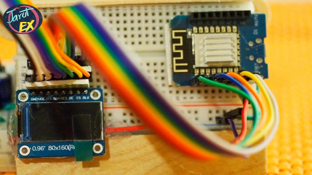
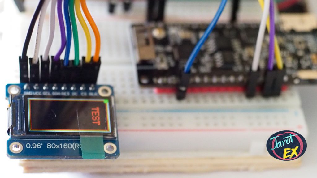
จากบทความ ST7735S 0.96″ 80×160 TFT LCD ได้กล่าวถึงคุณลักษณะและหน้าที่ของขาเชื่อมต่อพร้อมตัวอย่างการเชื่อมต่อกับ TTGO T8 ESP32 ไปเรียบร้อยแล้ว ในบทความนี้เป็นตัวอย่างการนำโมดูลแสดงผลมาใช้งานกับ ESP8266 ซึ่งมีขีดจำกัดในเรื่องของปริมาณหน่วยความจำที่น้อยกว่า ESP32 จึงต้องแก้ปัญหาด้วยการคอมไพล์ไลบรารีให้เป็นไบต์โค้ดนามสกุล mpy

บทความนี้แนะนำ TFT LCD แบบ IPS ขนาด 0.96″ ที่มีความละเอียด 80×160 จุด ให้สี RGB565 หรือ 16 บิต โดยควบคุมการทำงานของโมดูล LCD ด้วยชิพ ST7735s ผ่านทางบัส SPI โดยตัวอย่างการใช้งานใช้กับ TTGO T8 ESP32 ที่เรียกใช้ไลบรารี ST7735 ด้วยภาษาไพธอน


TTGO T8 ESP32 is an ESP32-powered board. Supports programming for ESP-IDF, Arduino and MicroPython. In addition, the highlight of this board is Built-in memory, 4MB external RAM available, TF Card reader slot, can read/write SD card, turn on/off switch, reset button, 3D antenna, external antenna socket, charging circuit and using a rechargeable battery.
บทความนี้เป็นตัวอย่างการใช้โมดูลอ่าน/เขียนการ์ดประเภท SD-Card เพื่อเก็บข้อมูลและอ่านข้อมูลในรูปแบบ JSON ซึ่งเป็นแนวทางสำหรับผู้อ่านบทความสามารถนำไปประยุกต์ใช้งานต่อไปในอนาคต

บทความนี้เป็นตัวอย่างการเขียนโปรแกรมภาษาไพธอนเพื่อขับโมดูรีเลย์เพื่อเปิด/ปิดหลอดแอลอีดีให้สว่างหรือดับผ่านการสั่งงาน WiFi ในโหมด AP ของ ESP8266

This article is a compiled article about time library usage related to the time delay of the ESP8266 along with an example of connecting to an NTP Server for synchronization.


TTGO T8 ESP32 เป็นบอร์ดที่ใช้ ESP32 เป็นตัวขับเคลื่อนการทำงาน รองรับการเขียนโปรแกรมทั้ง ESP-IDF, Arduino และ MicroPython นอกจากนี้จุดเด่นของบอร์ดรุ่นนี้อยู่ที่ มีหน่วยความจำแรมภายนอกให้ใช้งาน 4MB มีช่องอ่าน TF Card ทำให้สามารถอ่าน/เขียน SD Card ได้ มีสวิตช์สำหรับเปิดปิดการทำงานของบอร์ด ปุ่มรีเซ็ต เสาอากาศแบบ 3 มิติ ช่องเสียบสายอากาศภายนอก และวงจรชาร์จ/ใช้งานแบตเตอรีแบบรีชาร์จ
This article uses the ESP8266 to read the values from the soil moisture sensor. The appearance of the selected sensor is shown in Figure 1. The circuit of the sensor is shown in Figure 2 which there’s a part for the conversion of resistance from current flow to analog and digital values. In which the digital sector has to be rotated to adjust the resistance from the variable resistor. After that, the voltage obtained by adjusting the resistance is used as a comparator of the voltage obtained by the sensor circuit and output the data as a digital signal as a value of 0 or 1, but in this article choose to read the value from analog signal via A0, which is 10 bits analog to digital converter (ADC) consequently the value read from analog signal will be integer start from 0 to 1024. The example program is written in Python along with showing the converted values from the ADC displayed on the web page.