[TH] ESP8266 time Library
บทความนี้เป็นบทความที่เรียบเรียงข้อมูลเกี่ยวกับการใช้งานไลบรารี time ซึ่งเกี่ยวข้องกับการหน่วงเวลาของ ESP8266 พร้อมตัวอย่างการเชื่อมต่อกับ NTP Server เพื่อทำการซิงค์ เวลาให้ตรงกัน

บทความนี้เป็นบทความที่เรียบเรียงข้อมูลเกี่ยวกับการใช้งานไลบรารี time ซึ่งเกี่ยวข้องกับการหน่วงเวลาของ ESP8266 พร้อมตัวอย่างการเชื่อมต่อกับ NTP Server เพื่อทำการซิงค์ เวลาให้ตรงกัน

บทความนี้เป็นการนำ ESP8266 มาใช้อ่านค่าจากเซ็นเซอร์ความชื้นของดิน ซึ่งหน้าตาของเซ็นเซอร์ที่เลือกใช้เป็นดังภาพที่ 1 โดยวงจรของการทำงานตามภาพที่ 2 จะมีส่วนของการแปลงความต้านทานจากการไหลของกระแสไฟเป็นค่าแบบแอนาล็อกและดิจิทัล ซึ่งในภาคของดิจิทัลนั้นต้องทำการหมุนเพื่อปรับค่าความต้านทานจากตัวต้านทานปรับค่าได้ หลังจากนั้นค่าแรงดันที่ได้จากการปรับค่าความต้านทานจะถูกใช้เป็นตัวเปรียบเทียบแรงดันที่ได้รับจากวงจรเซ็นเซอร์ และนำออกข้อมูลเป็นสัญญาณดิจิทัลเป็นค่า 0 หรือ 1 แต่ในบทความนี้เลือกใช้การอ่านค่าจากสัญญาณแอนาล็อกผ่านเข้าทางขา A0 ซึ่งเป็นภาคแปลงสัญญาณแอนาล็อกเป็นดิจิทัล (ADC: Analog to Digital Converter) ขนาด 10 บิต ทำให้อ่านค่าแรงดันที่ได้รับเป็นค่าจำนวนเต็มในช่วง 0 ถึง 1024 โดยตัวอย่างโปรแกรมเขียนด้วยภาษาไพธอน พร้อมแสดงค่าที่แปลงจาก ADC แสดงผ่านเว็บ
The ESP8266 is a device with a built-in WiFi connection system that can operate in both AP (Access Point) mode and client mode connected to an existing WiFi network or STA. The developer can set the name of the device (ESSID) or use the name according to the value set by the system to MicroPython-xxxx, where x represents the MAC Address of the device, the password is micropythoN (the developer can define a new one) with the IP address (IP Address) of 192.168.4.1.

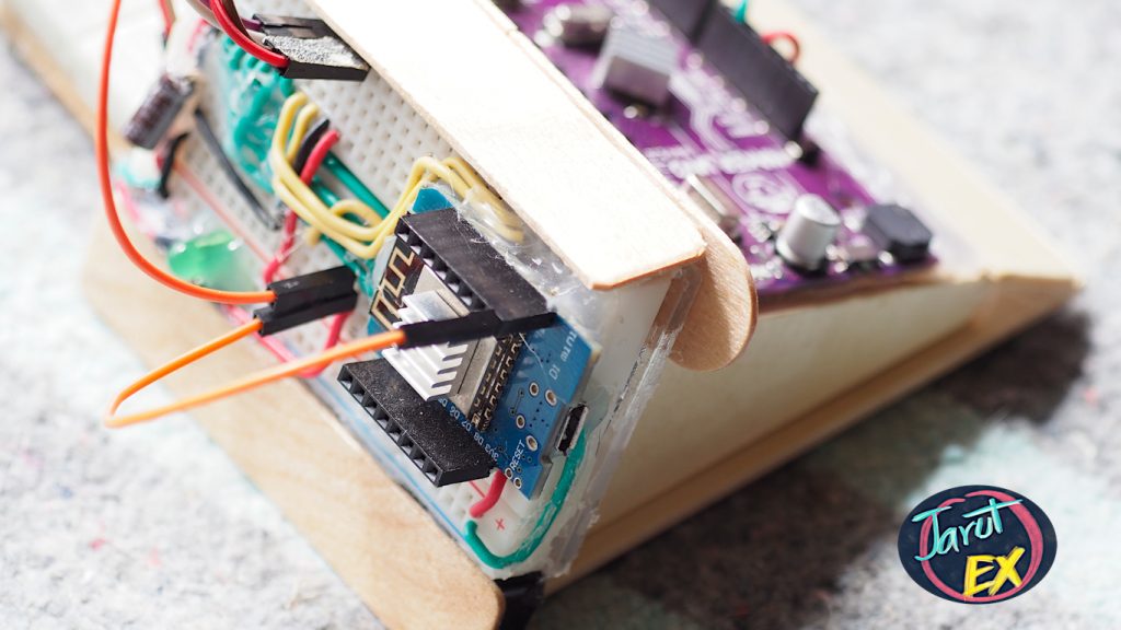
ESP8266 is a device that nicely supports IoT functionality. But one of the downsides of the ESP8266 is the inadequate number of GPIOs or pins for input and output signals that can be used without a problem with the board’s functionality, so expanding ports for the ESP8266 is quite a thing that developers must be faced which can be performed in a several ways such as using PCF8574 as an expansion port via the I2C bus or connecting to Arduino via Serial Port to allow Arduino to work and send the results back via the serial communication port, etc. This article chose to use an Arduino Uno as a board for I / O to the ESP8266 by using the I2C bus operation.
(วิธีการทำให้ “ESP8266” อ่านและเขียนไปยัง “Arduino UNO Maker” ผ่านบัส I2C.)
ESP8266 เป็นอุปกรณ์ที่รองรับการทำงานแบบ IoT ได้เป็นอย่างดี แต่ข้อเสียประการหนึ่งของ ESP8266 คือ จำนวน GPIO หรือขาสำหรับนำเข้าสัญญาณและนำออกสัญญาณที่สามารถใช้งานได้โดยไม่เป็นปัญหากับการทำงานของบอร์ดมีไม่มากนัก ดังนั้น การขยายพอร์ตให้กับ ESP8266 จึงเป็นสิ่งที่นักพัฒนาต้องประสบพบเจอ ซึ่งสามารถเลือกดำเนินการได้หลายวิธี เช่น ใช้ PCF8574 เป็นพอร์ตขยายผ่านทางบัส I2C หรือเชื่อมต่อกับ Arduino ผ่านทางพอร์ตสื่อสารอนุกรม (Serial Port) เพื่อให้ Arduino เป็นผู้ทำงานและส่งผลลัพธ์กลับมาทางพอร์ตสื่อสารอนุกรม เป็นต้น โดยในบทความนี้เลือกการใช้ Arduino Uno เป็นบอร์ดสำหรับเป็น I/O ให้กับ ESP8266 โดยอาศัยการสั่งงานผ่านทางบัส I2C
WeMos D1 Pro Mini is an ESP8266 board with 16MB Flash ROM memory, useful for taking unaltered images or data stored in Flash ROM for later usage. However, when flashing MicroPython firmware onto this board, there are steps that need to be done in addition to writing with the 4MB version of the board. (The method for the WeMos D1 R1 mini or ESP8266 board can be seen from this video) In this article, we will try to flash ROM and write a program to display board information.

WeMos D1 Pro Mini เป็นบอร์ด ESP8266 ที่มีหน่วยความจำ Flash ROM ให้ใช้งาน 16MB ซึ่งมีประโยชน์การนำข้อมูลภาพหรือข้อมูลที่ไม่มีการเปลี่ยนแปลงจัดเก็บไว้ใน Flash ROM และนำมาใช้งาน แต่อย่างไรก็ดี การเขียน Firmware MicroPython ลงบนบอร์ดนี้จะมีขั้นตอนที่ต้องทำเพิ่มจากการเขียนกับบอร์ดรุ่น 4MB (วิธีการของบอร์ด WeMos D1 R1 mini หรือ ESP8266 สามารถดูได้จากคลิปนี้ครับ … gogogo …) ในบทความนี้เราจะทดลองเขียน ROM และเขียนโปรแกรมเพื่อแสดงข้อมูลของบอร์ดกันครับ
