[EN] Control movement from a joystick via WiFi with MicroPython.

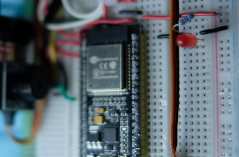
This article is based on the article programming a client/server for a weather station over a wireless network or WiFi to modify from reading data from sensors to joystick shield (Arduino Joystick Shield) so that it has become a wireless game controller using MicroPython and an ESP32 microcontroller as shown in Figure 1. It is possible to control the movement of objects in the display via a ST7735 TFT screen connected to another ESP32. It will be found that the Python implementation of MicroPython is applicable in this example. And with an easy-to-write language and code that can be modified without recompiling and uploading, it’s easy to write prototype code for further development at a higher speed.
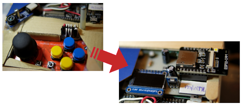
Control movement from a joystick via WiFi
(Figure. 1 Our board)

[TH] Arduino: ควบคุมการเคลื่อนที่หุ่นยนต์รถผ่านบราวเซอร์ด้วย esp8266

จากบทความการควบคุมหุ่นยนต์รถ 2 ล้อแบบ Servo ใน ESP8266+RoboServo และมอเตอร์ไฟฟ้ากระแสตรงใน VisionRobo Car: Drive Motor ทางเราได้นำหุ่นยนต์รถในตัวที่ 2 เปลี่ยนจาก Raspberry Pi เป็น ESP8266 เพื่อสั่งงานผ่าน WiFi โดยใช้แนวทางจาก บทความ ESP-01s+Relay มาเขียนใหม่ด้วยภาษา C/C++ ของ Arduino ด้วยคลาส WebServer จากที่ในบทความของ ESP8266 เป็น MicroPython ดังนั้น เมื่อทำตามบทความนี้จนเสร็จจะสามารถสั่งงานหุ่นบนต์ในภาพตัวอย่างที่ 1 ได้ด้วยการเชื่อมต่อโทรศัพท์หรืออุปกรณ์สื่อสารไปที่ 192.168.4.1 และสั่งให้เดินหน้า ถอยหลัง เลี้ยวซ้าย เลี้ยวขวา หรือหยุดได้

ภาพที่ 1 ตัวอย่างหุ่นยนต์รถสำหรับการทดลองในบทความนี้

[EN] ESP-IDF Ep.9 : LEDC (PWM) Output

This article discusses the use of the ESP32’s GPIO to output digital signals such as PWM or Pulse Width Modulation or LEDC (LED Control), which enables frequency generation or adjusts the proportion of 1 and 0 states in 1 waveform. Thus, in the absence of the DAC, we can still adjust the average voltage at that pin as needed and it can be applied to control servo motors as well. Therefore, in this article, we will learn how to use PWM and apply it to frequency transmission instead of DAC (from the previous article) and LED dimming using the experimental board as shown in Figure 1.

LEDC / PWM Labs.
(Figure. 1 Our LEDC)

[TH] Generate temperature and humidity graphs with data from Singly Linked List.

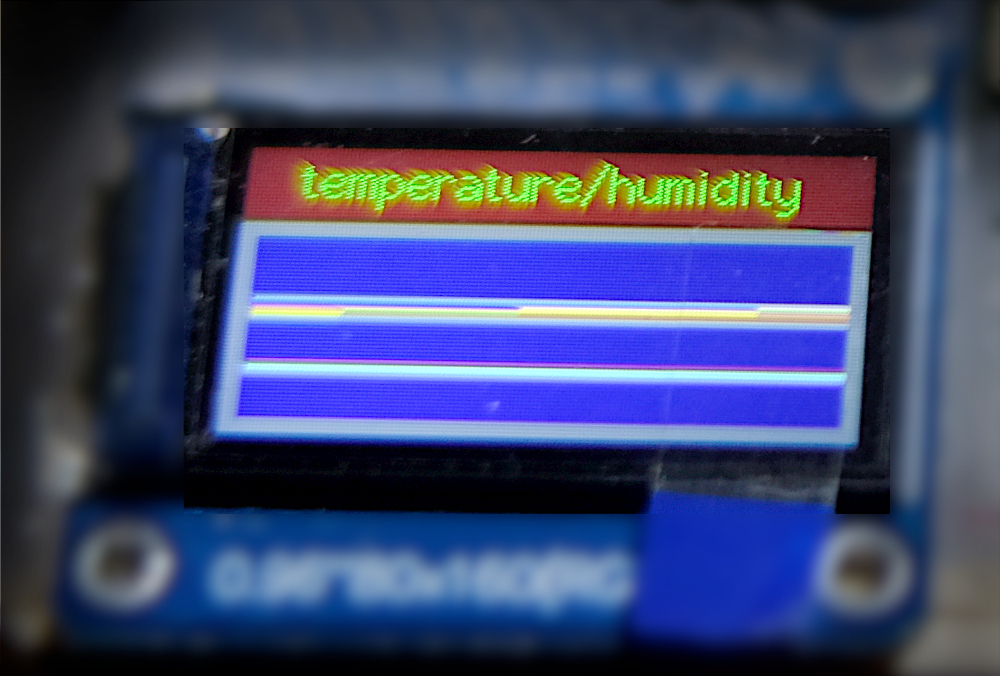
จากบทความโครงสร้างข้อมูล Singly Linked List, การใช้โมดูลเซ็นเซอร์ DHT11 กับไมโครคอนโทรลเลอร์ STM32F103 และการใช้โมดูลแสดงผล TFT ที่ใช้ตัวควบคุม st7735s จึงเกิดเป็นแนวคิดของบทความนี้ คือ นำตัวอย่างการใช้โครงสร้างข้อมูลแบบลิงค์ลิสต์เดี่ยวที่เก็บค่าอุณหภูมิและความชื้นมาหาค่ามากสุด น้อยสุด ค่าเฉลี่ย พร้อมทั้งข้อมูลในลิสต์มาแสดงในรูปแบบของกราฟดังภาพที่ 1

ภาพที่ 1 ตัวอย่างผลลัพธ์ที่ได้จากบทความนี้

[EN] ESP-IDF Ep.8 : DAC Output Part 2

This article discusses the use of the ESP32’s GPIO as an analog signal output through the 8-bit DAC module of the ESP32 microcontroller. In this article, we use Cosine wave generation to output the analog signal of the microcontroller through the speaker and show the waveform obtained from the oscilloscope display. The experimental board is still used as shown in Figure 1.

(Figure. 1 Connection and use of DAC examples)

[TH] Singly Linked List

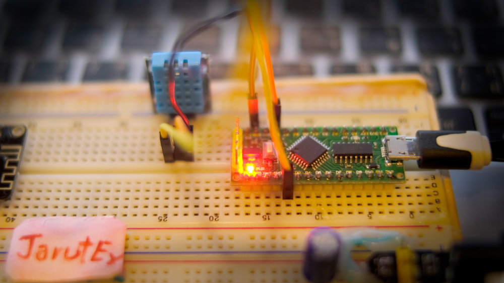
บทความนี้เป็นการเขียนโปรแกรมภาษา C/C++ กับบอร์ด Arduino Nano, Arduino Uno, LGT8F328P หรือบอร์ดอื่น ๆ และแพล็ตฟอร์มอื่น ๆ ที่ใช้ภาษา C ได้ โดยในบทความนี้กล่าวถึงวิธีการใช้โครงสร้าง struct สำหรับเก็บข้อมูลและตัวชี้ที่ใช้สำหรับชี้ไปยังตำแหน่งของหน่วยความจำ และวิธีการบริหารหน่วยความจำได้แก่ การจองหน่วยความจำ การเข้าถึงหน่วยความจำ และการยกเลิกการใช้หน่วยความจำเพื่อสร้างวิธีการจัดเก้บข้อมูลแบบลิงค์ลิวต์เดียว (Singly Linked List) พร้อมทั้งตัวอย่างโปรแกรมที่ใช้สำหรับเก็บรายการค่าอุณหภูมิและความชื้นจากโมดูล DHT11 ดังภาพที่ 1

ภาพที่ 1 บอร์ดไมโครคอนโทรลเลอร์ที่ใช้ชิพ LGT8F328P กับโมดูล DHT11

[EN] ESP-IDF Ep.6 : ADC Input

This article discusses the use of the ESP32’s GPIO as an analog input. By using the voltage input circuit from adjusting values with an adjustable resistor as shown in Figure 1. So, in this article, we will learn how to use the ADC instruction of the ESP32 microcontroller and how to configure the value of ADC in menuconfig.

(Figure. 1 The implementation is illustrated with the example in this article)

[EN] How to used Arduino 2.4″ TFT LCD&Touch Shield with STM32F401?

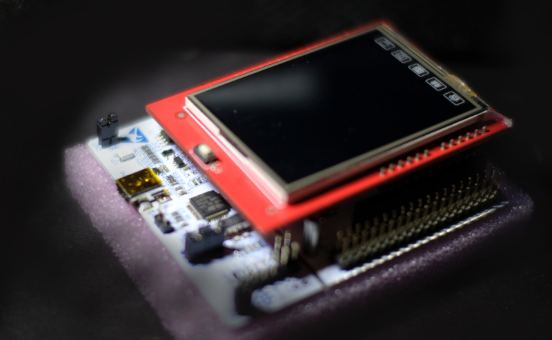
From the previous article that has used a 3.5″ display for Raspberry Pi Board to use with ESP32, we also have an Arduino 2.4″ TFT LCD & Touch Shield that is used with Arduino Uno and Arduino Mega (as shown in Figure 1. ) and want to use with a microcontroller STM32F401RET6 Board NUCLEO-F401RE and STM32F401CC (Figure 2), which are Cortex-M4 with 96KB and 64KB memory respectively, ROM memory is 512KB and 128KB, with 8 switches connected to the pin. In this article, Board ET-TEST 10P/INP (Figure 3) is used to replace the left, up, down, right, m1,m2, A and B buttons respectively.

Nucleo-F401RE+Arduino Uno 2.4" TFT&Touch Shield
(Figure. 1 Arduino Uno TFT&Touch Shield module on Nucleo-F401RE)