[EN] ESP32 machine.Timer

This article discusses the use of 4 timers of the ESP32 to be used to run the program when it meets the specified time. Difference Between Using Timer and Delay time.sleep()/time.sleep_ms()/time.sleep_us() is that time delay is a loop to allow the processor to spend time looping to complete the specified amount of time whereas the timer uses the principle of having a function run every time a specified time is reached, so while a timer does not call a function to execute the processor has idle time for other processing, and unlike interrupts, it is a timer interrupt instead of a pin state interrupt connected to an external circuit.

[EN] Arduino : DHT Sensor

This article describes how Adafruit’s DHT Sensor library is compatible with all Arduino-compatible architectures, making it easier to deploy DHT sensors for humidity and temperature readings across multiple platforms. This article has tested with ESP32, ESP8266, Arduino UNO and stm32f103c and found that it can be used without modifying the code in the working part or having to modify the source code to make it compatible with the platform.

(Figure. 1 dht22 and BluePill)

[EN] Arduino: JoyStick Shield

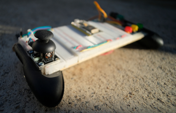
This article is a guideline on using GamePad/Joystick with Arduino Uno or Arduino Mega because it is a module designed as a shield of both boards. When assembled, you will get 1 cute gamepad as shown in Figure 1. The article explains more about the information of the connection between each device and the GPIO with examples of use. The content about the joystick module can be read from the previous article.

(Figure. 1 Joystick Shield)

[EN] Arduino: Joystick Module

This article is programming to write a program to use the joystick module as shown in Figure 1, in which the module can tell the X-axis movement, Y-axis movement, and the state of pressing the switch on the joystick. An example of this module is to use the esp32 board using C++ to connect to the GPIO using the commands mentioned in this article.

(Figure. 1 esp32 with joystick

[TH] ESP-IDF Ep.10 : Control the Servo Motor with LEDC.

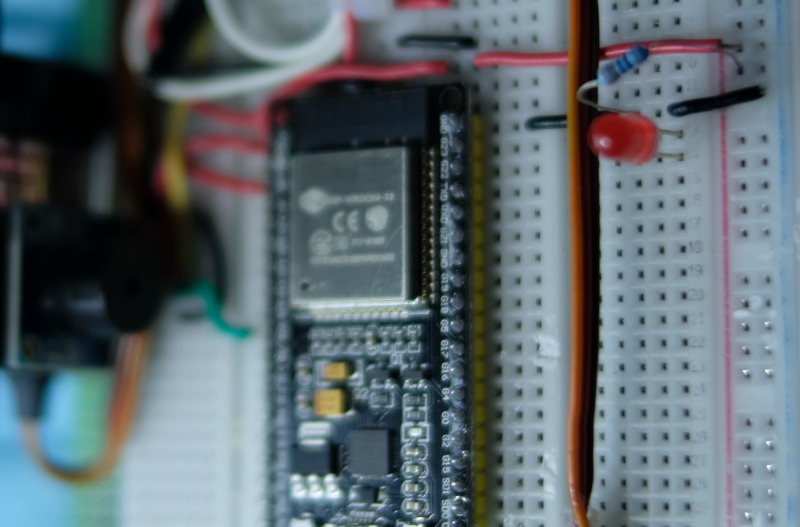
บทความนี้กล่าวถึงการใช้งานโมดูลเซอร์โวมอเตอร์ด้วยการใช้ GPIO ของ ESP32 ที่นำออกสัญญาณดิจิทัลแบบ PWM หรือ Pulse Width Modulation หรือ LEDC (LED Control) ซึ่งทำให้สามารถสร้างคลื่นความถี่ หรือปรับสัดส่วนของสถานะ 1 และ 0 ใน 1 ลูกคลื่น ที่มีความถี่ 50Hz โดยใช้บอร์ดทดลองดังภาพที่ 1

ภาพที่ 1 การต่อใช้งานประกอบตัวอย่างการใช้งาน LEDC

[TH] Control movement from a joystick via WiFi with MicroPython.

บทความนี้เกิดจากการนำบทความการเขียนโปรแกรมไคลเอนต์/เซิร์ฟเวอร์สำหรับสถานีอากาศผ่านระบบเครือข่ายไร้สาย หรือ WiFi มาปรับเปลี่ยนจากการอ่านข้อมูลจากเซ็นเซอร์มาเป็นจอยสติกชิลด์ (Arduino Joystick Shield) เพื่อให้กลายเป็นเกมคอนโทรลเลอร์แบบไร้สายโดยใช้ MycroPython กับไมโครคอนโทรลเลอร์ ESP32 ดังภาพที่ 1 ทำให้สามารถควบคุมการเคลื่อนที่ของวัตถุในจอแสดงผลผ่านจอ TFT แบบ ST7735 ที่เชื่อมต่อกับ ESP32 อีกตัวหนึ่งได้ ซึ่งจะพบว่าการใช้งานภาษาไพธอนของ MicroPython นั้นสามารถนำมาใช้งานได้กับกรณีตัวอย่างนี้ และด้วยภาษาที่เขียนได้ง่ายประกอบกับสามารถปรับแก้โค้ดได้โดยไม่ต้องคอมไพล์และอัพโหลดใหม่จึงสะดวกต่อการเขียนโค้ดต้นแบบเพื่อนำไปพัฒนาให้มีความเร็วในการทำงานที่สูงขึ้นต่อไป

Control movement from a joystick via WiFi
ภาพที่ 1 อุปกรณ์การทดลองในบทความ

[TH] ESP-IDF Ep.9 : LEDC (PWM) Output

บทความนี้กล่าวถึงการใช้งาน GPIO ของ ESP32 เพื่อทำหน้าที่นำออกสัญญาณดิจิทัลแบบ PWM หรือ Pulse Width Modulation หรือ LEDC (LED Control) ซึ่งทำให้สามารถสร้างคลื่นความถี่ หรือปรับสัดส่วนของสถานะ 1 และ 0 ใน 1 ลูกคลื่น ด้วยเหตุนี้ในกรณีที่ไม่มีภาค DAC ผู้เขียนยังคงสามารถปรับค่าเฉลี่ยของแรงดันที่ขานั้นได้ตามที่ต้องการ และสามารถประยุกต์ใช้ในการควบคุมมอเตอร์แบบเซอโวได้อีกด้วย ดังนั้น ในบทความนี้จึงเป็นการเรียนรู้การใช้งาน PWM และประยุกต์เข้ากับการส่งคลื่นความถี่แทน DAC  (จากบทความที่แล้ว) และการหรี่หลอดแอลอีดี โดยใช้บอร์ดทดลองดังภาพที่ 1

LEDC / PWM Labs.
ภาพที่ 1 การต่อใช้งานประกอบตัวอย่างการใช้งาน LEDC

[TH] ESP-IDF Ep.8 : DAC Output Part 2

บทความนี้กล่าวถึงการใช้งาน GPIO ของ ESP32 เพื่อทำหน้าที่นำออกสัญญาณแอนาล็อกผ่านทางโมดูล DAC ขนาด 8 บิตของไมโครคอนโทรลเลอร์ ESP32 ต่อจากคราวที่แล้ว โดยในบทความนี้เป็นการใช้การสร้างคลื่นแบบ Cosine เพื่อนำออกสัญญาณแอนาล็อกของไมโครคอนโทรลเลอร์ผ่านลำโพง และแสดงให้เห็นรูปของคลื่นที่ได้จากจอแสดงผลของออสซิโลสโคป ส่วนบอร์ดทดลองยังคงใช้ตามภาพที่ 1

ภาพที่ 1 การต่อใช้งานประกอบตัวอย่างการใช้งาน DAC